Fixing See-Fun's (Seeburg's) Olympic Tennis (1973)
Just another Pong Doubles clone...
The Olympic Tennis boards were the first two Arcade PCBs that I ever owned. I bought them when I was 14, from the guys at the Chattanooga Pinball Company. At the time, I was very excited. I had been hoping to own a few arcade games since I was... 6? 8? Because I had recently just started mowing the lawn, I was finally able to afford them.
Let me tell you the story of how I acquired these boards.
Since I had been saving up for awhile, I decided it was time to start looking on Ebay for my first game.
I was doing specific search terms, since I knew what I wanted: Atari Pong, Pong Doubles, Space Race, Gotcha, Quadrapong, Gran Trak 10, etc. After searching Space Race, I was delighted to see not one, but THREE boards marked as 'Space Race'. After looking closer, I realized that they weren't Space Races. They had no array of diodes shaped like a rocket ship. They were Pong clones. There were no other relevant results for any of my searches, so I just kept waiting for a few months.
I kept seeing those boards. They were starting to bother me. I knew those weren't regular PONGs, because they used around 90 chips and Pong used about 60. I looked even closer, and I also saw it had 4 NE555 timers instead of 2 in the paddle area of Pong. Then I realized: THIS IS NOT A PONG CLONE, THIS IS A PONG DOUBLES CLONE!
I wanted Pong Doubles, so I figured: "Why not?" I knew I already had all the chips I would need to fix it, because a few years back I unsuccessfully tried to clone Pong. (Here's the story...)
I bought the remaining two. (Ed Fries bought the third one, see this article within his website: Fixing Color Gotcha)
(I acutally wanted to buy that one, because it came with an edge connector...)
Here they are, after they arrived:
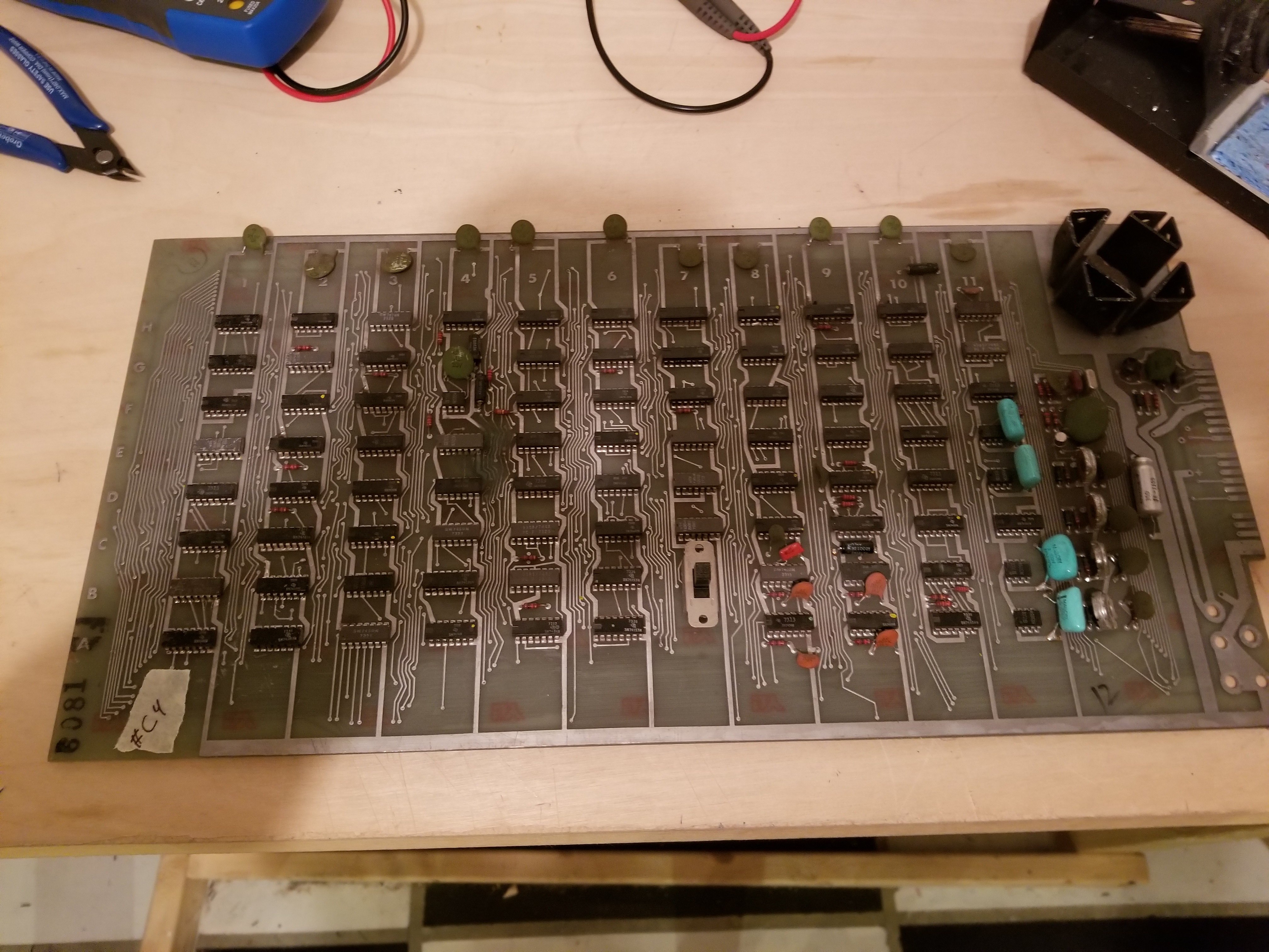
After buying them, I realized that they did not conform to the Pong Doubles Pinout.
Well, no problem, I can figure out the pinout by myself...
The first step to doing that is to find the +5 volts and ground on the edge connector. A multimeter set to resistance should do the trick.
Next, find the Video output signal. That *should* be easy, because that is the only square-ish wave output on a discrete arcade PCB. (Well, except for sound, but that only happens if a game is in progress, so I just discounted that.)
I tried to do that on one PCB, but there was no signal. Okay, there must just be a bad gate in the Sync Generation circuit, so I just tried the other board.
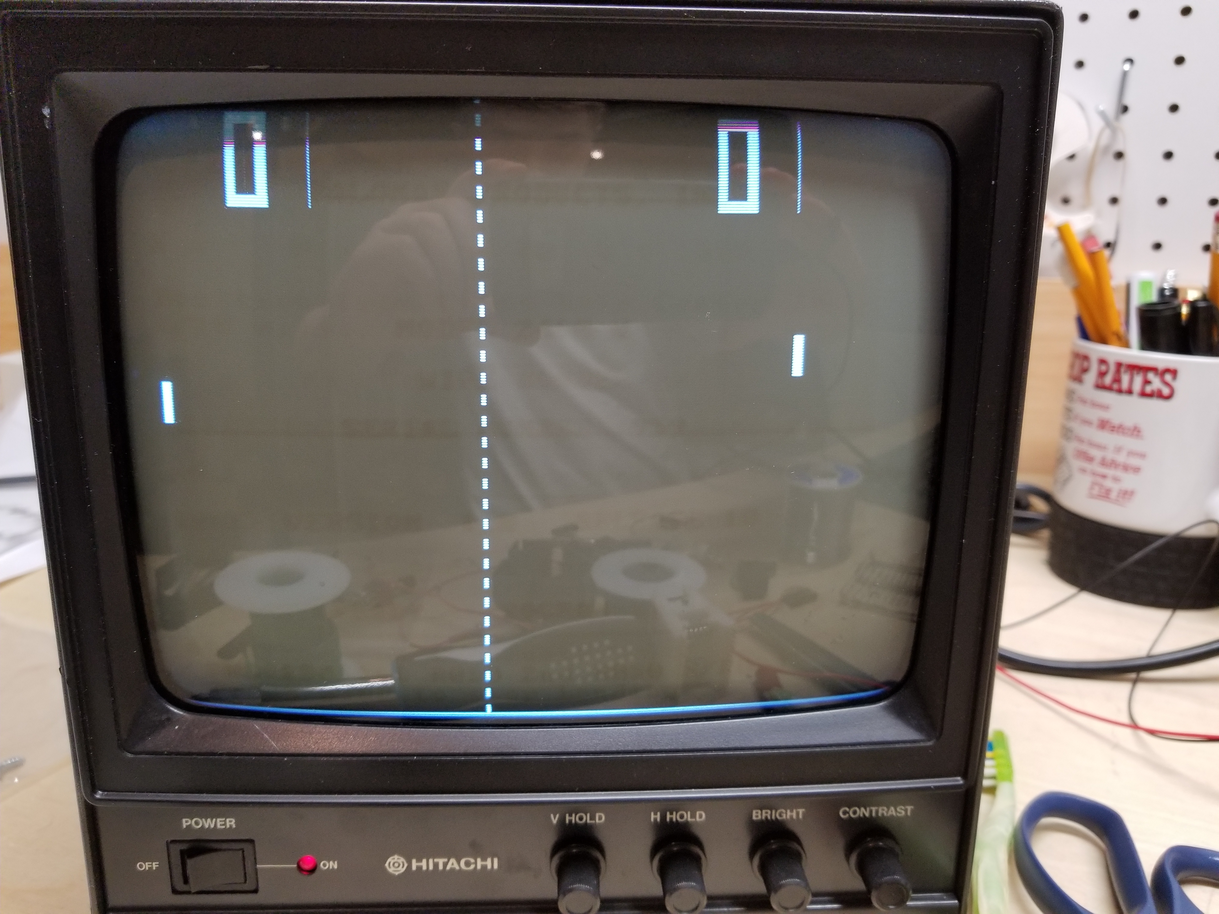
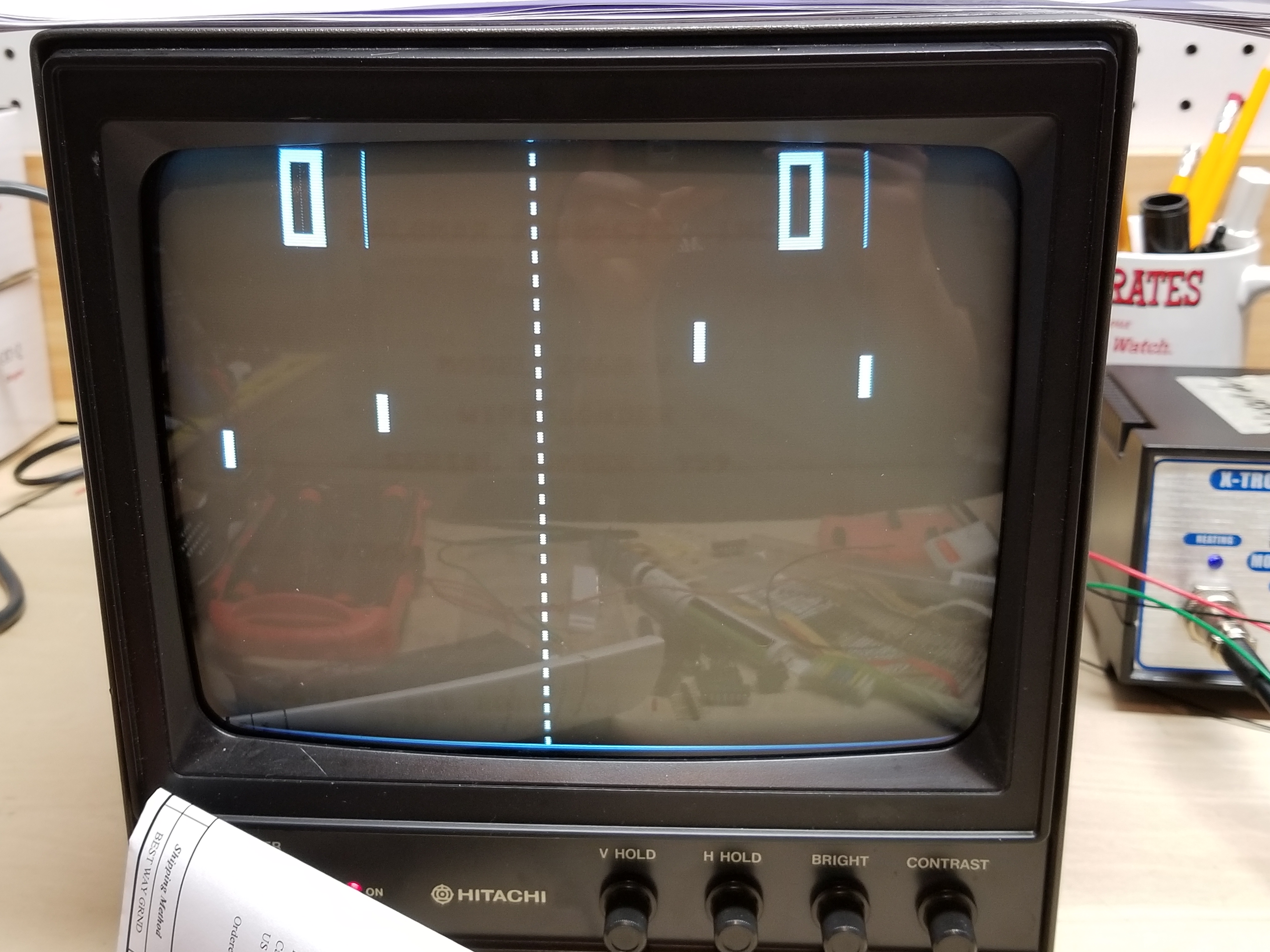
Sure enough, this appeared:
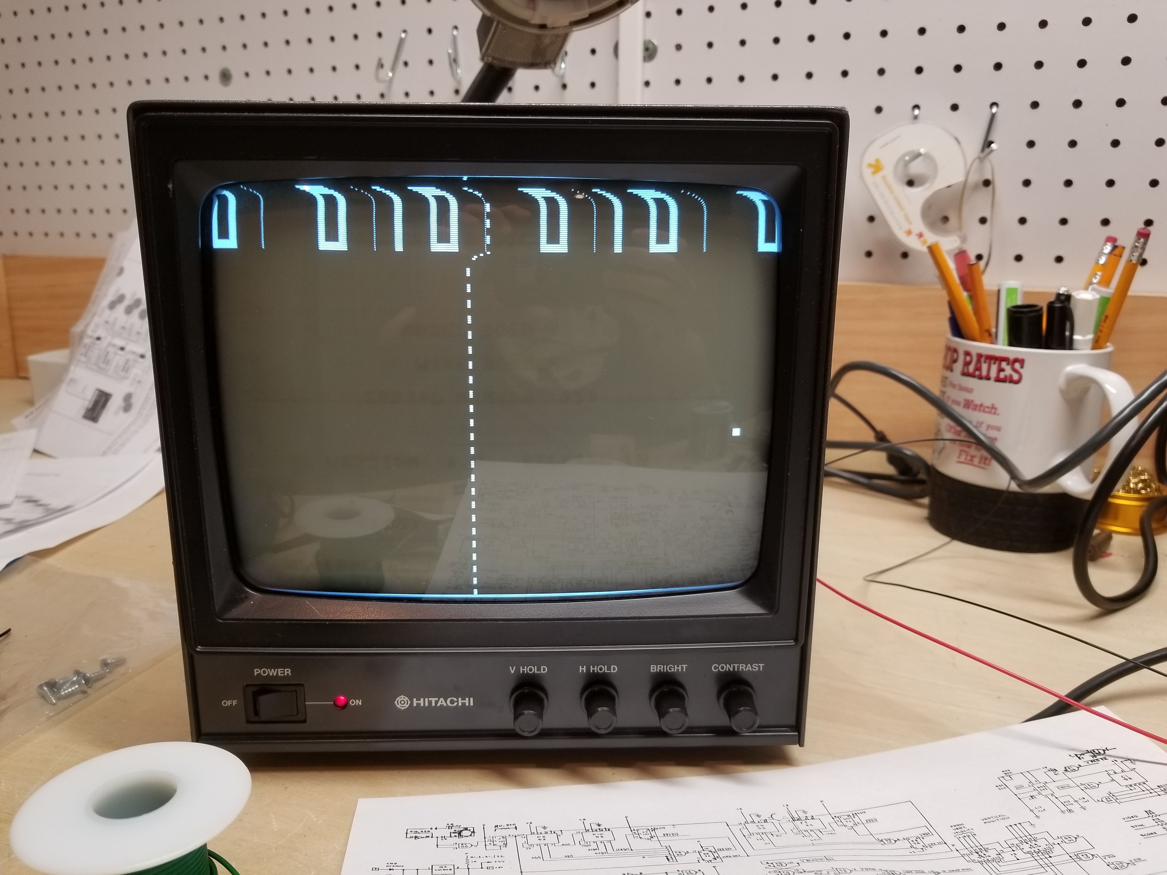
Is is just me, or are there too many scores?
The next thing I decided to do, was find the paddle outputs. From looking at the Pong Doubles schematics, I guessed there would be about 470 ohms of resistance between pin 5 on the NE555 timers, and their respective pin on the edge connector.
It turned out that I was right.
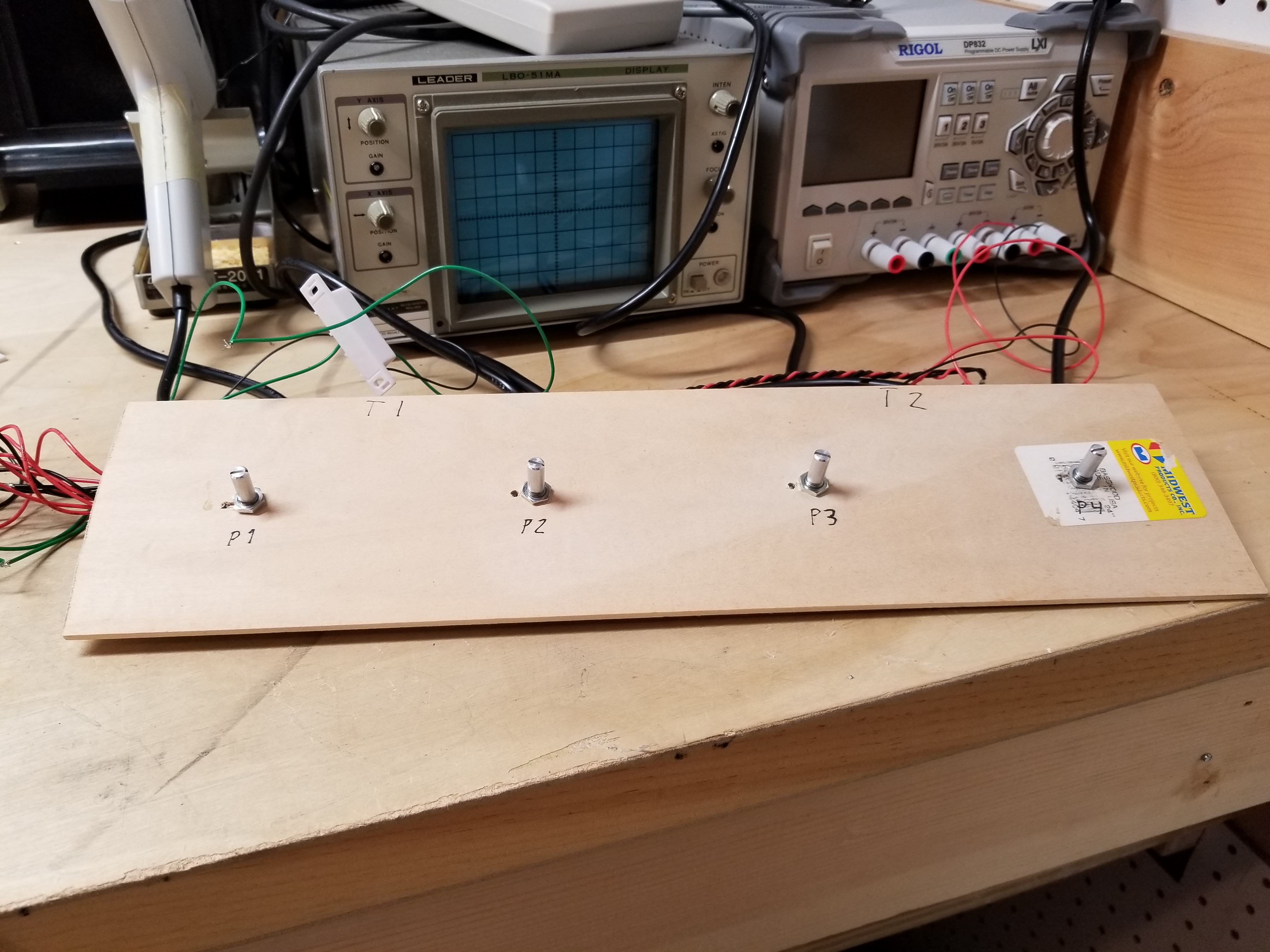
I could not for the life of me figure out how to find the coin switch or start button.
About half a year passed. In doing research about B/W video games, I discovered that the wiring loom I put together so far actually matched Allied Leisure's Tennis Tourney pinout. Sadly, the schematic did not match the board.
I tried wiring up the switches like they indicated, and sure enough, they worked. The game would not start, but the score would reset. Since I figured it was not a coincidence that the pinouts matched, I proceded in search of bad chips.
I had previously decided that because I did not have a schematic, I was just going to bite the bullet and check every single gate and every single chip with my Oscilloscope and a truth table.
I solved every problem (more on that later), except for the game not starting. I had run out of ideas. Looking at the board, I saw a single transistor looking at me. Since Pong used transistors in the coin circuit, I figured it may have been the problem.
Turns out, I was right.
And now, this would appear when I triggered the right switches.
Allied Leisure used a magnetic switch on Tennis Tourney, and I used one, too. I had not realized then that I could just use a regular leaf switch since the schematic just needed a normally closed/normally open switch, of which the magnetic switch was a type.
VICTORY!
Repairs for the board marked "C-4"
| The Problem: | Game Screen: | Solution: | How I found it: | Misc. |
| Net was a solid line, screen was out of sync. | N/A | Bad 7400 @ C1 | I piggybacked a good chip on top of it. | I did this repair before I started properly documenting my repairs. I scribbled it onto a piece of paper. |
| The game's clock signal would not start on its own. | N/A | Piggyback an ADDITIONAL 7404 on F11 to wrestle the voltage output of the clock signal higher.
(Only do this if you have already shotgunned the clock circuit.) |
I had a similar problem when I cloned pong... | " "
Also: This is a KLUDGE, not an actual repair. I shotgunned the clock circuit already. I may have put in a capacitor that was out of spec. |
| Too Many Scores,
Score area slightly out of sync. |
|
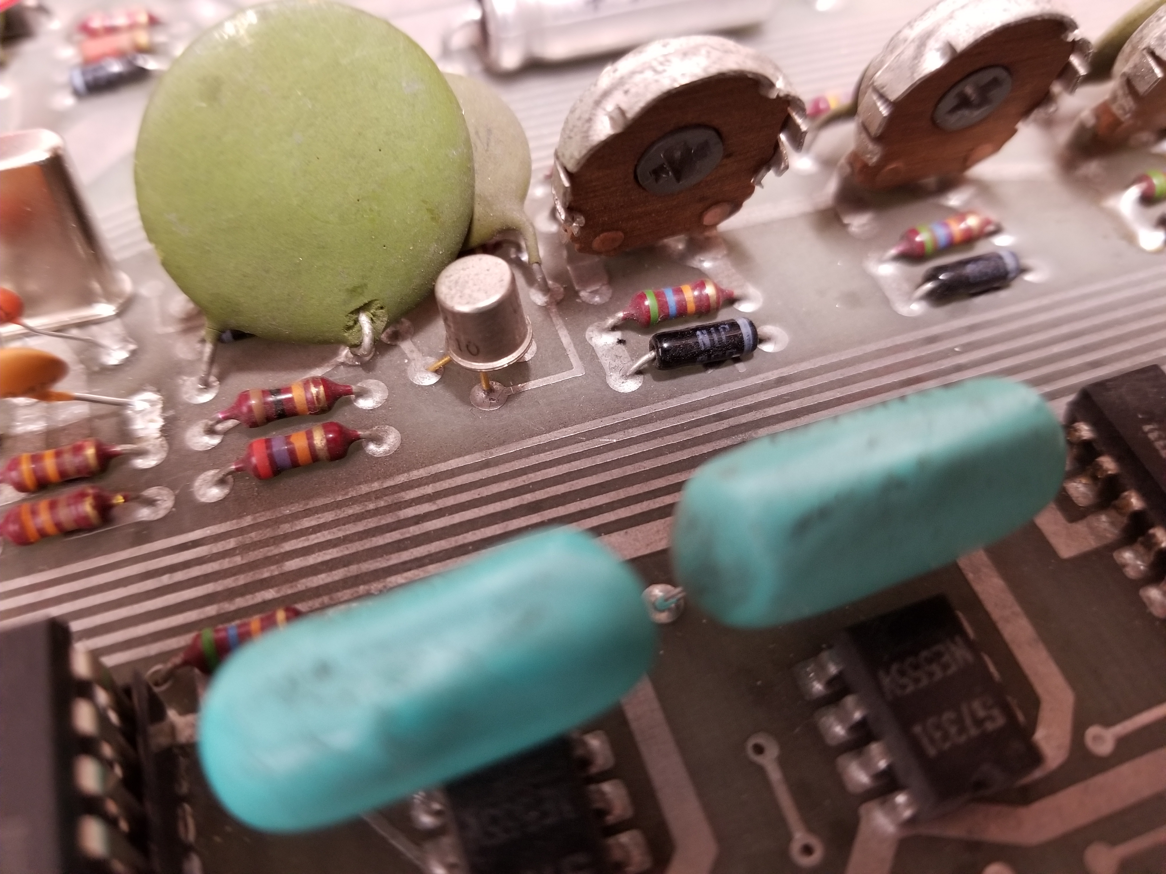
Solution: Bad 7423 at grid location F3. | I was checking every chip on the board. The 7423s were the last I checked. Both of the gates on this one had good inputs, but floating outputs. | The board had creative way of putting these on...
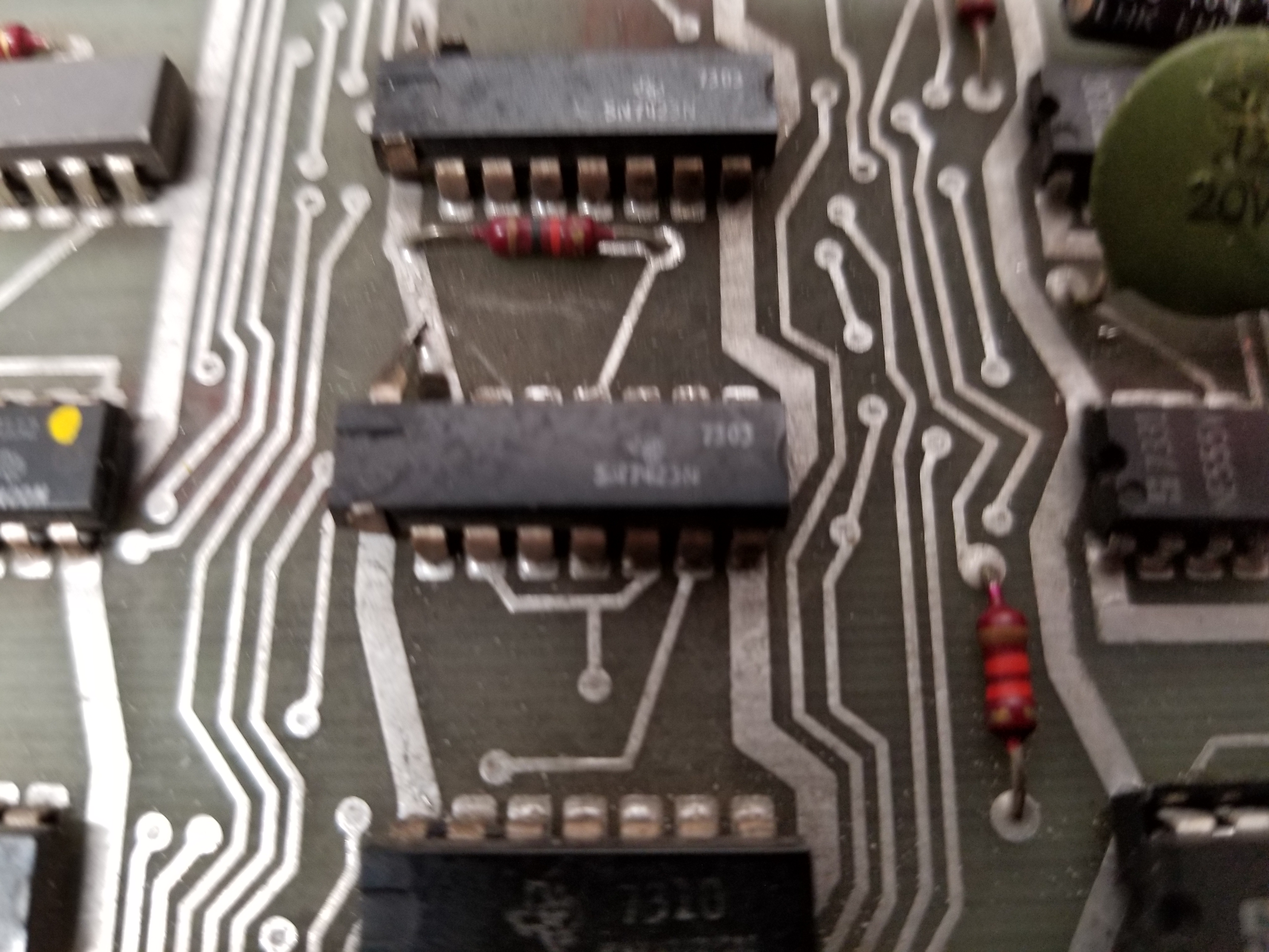
(Cut and lift pins 1 and 15, bend pin 16 to touch the power trace...) |
| Game would not coin up. | N/A | I had to replace several chips, but the
74107 @ B1, finally made it work.
There were probably other chips... Some of the 7474s were probably responsible... |
I checked all the 7474s and 74107s. | |
| The Game would not start when coined up... (The score would reset, but the game would not start.) | N/A | Bad 2N2222A Transistor | I had replaced every 7474 and 74107 with problems.
It was the only thing left that I could think of. |
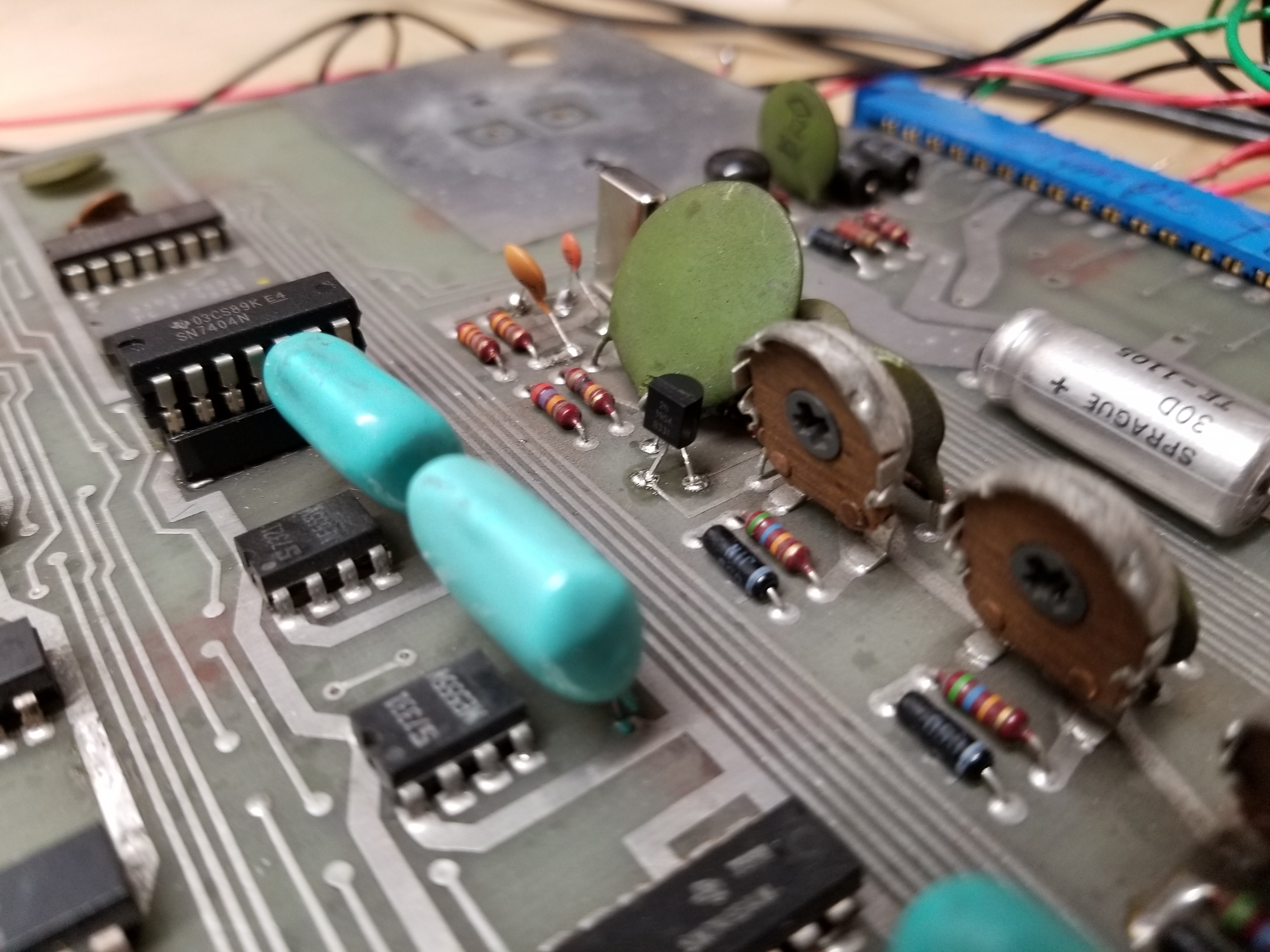
Here it is: (The tin can.)
Replaced:
|
| Random Paddles sometimes stretch to the bottom of the screen. | The problem was not there long enough to take a picture. | I have yet to fix it. | I don't know yet. | I have not been able to make the problem re-appear. I believe it is a certain 5uf capacitor on the board. When I put my finger on it, the problem goes away. If I take my finger away, it would stop working. |
| I just happened to discover dead or floating gates. | N/A | These are in the order I found them, I did not list chips that fixed something noticeable.
These were found bad: (in order)
|
I checked every gate on every chip... |
The 7474 @ D8 has something to do with paddles 2 and 3
The 7474 @ H3 has something to do with paddles 1 and 4 The 7400 @ H8 has something to do with ball collisions... I found all this out by turning the game on with the chips removed... (I had put in sockets.) |
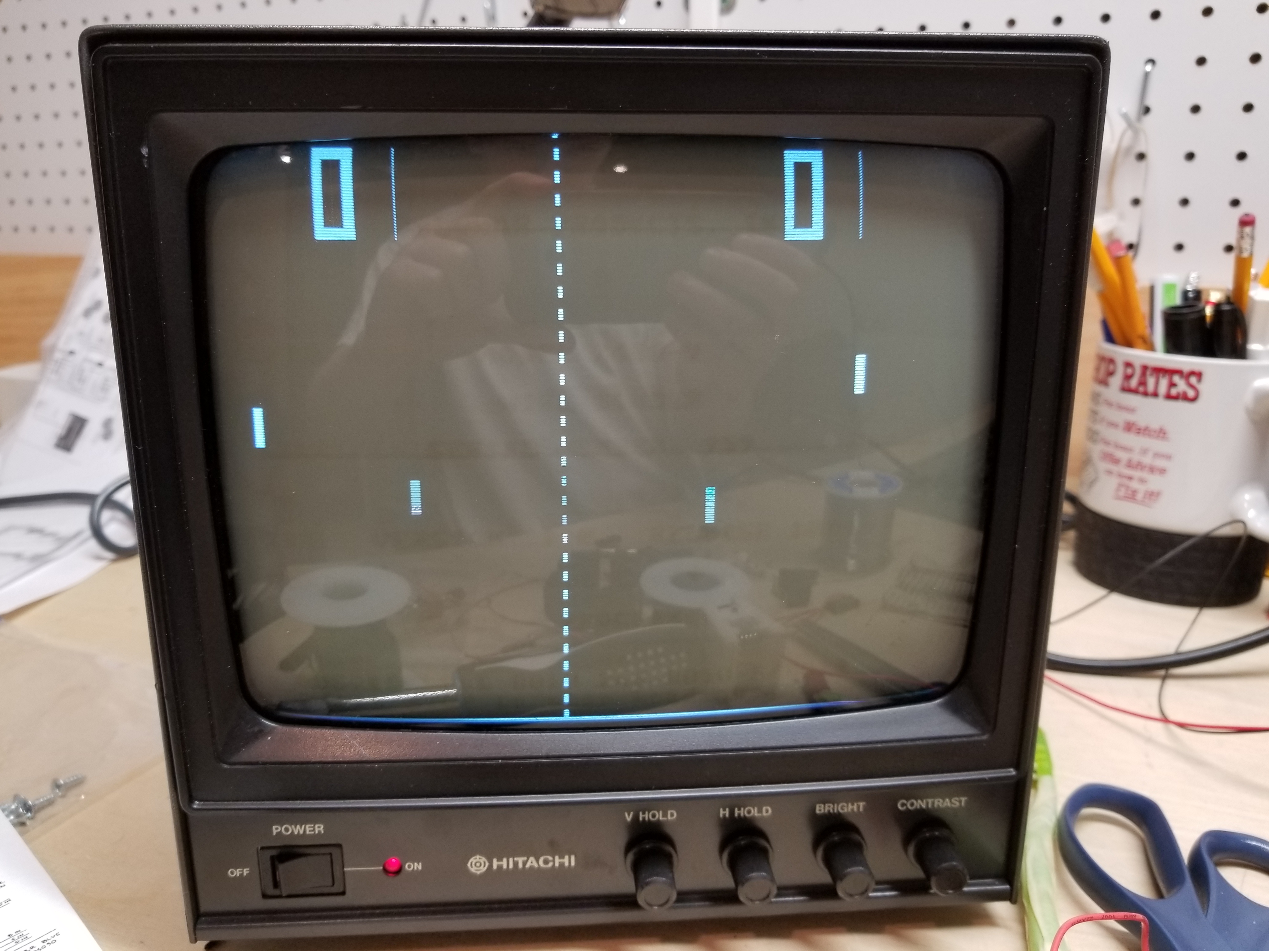
| Ball takes forvever / does not serve. | It would just remain like this: (With the score sound in the background. The two problems were discovered the same time I turned it on.)
Also: In this picture the paddles are (from left to right) 14,14,14, and 15 pixels tall. I just found that interesting, since people say the paddles are always 16 pixels tall... (Well, the circuitry technically makes them 16px tall, some components must have gone slightly out of spec in the past 40 years...) |
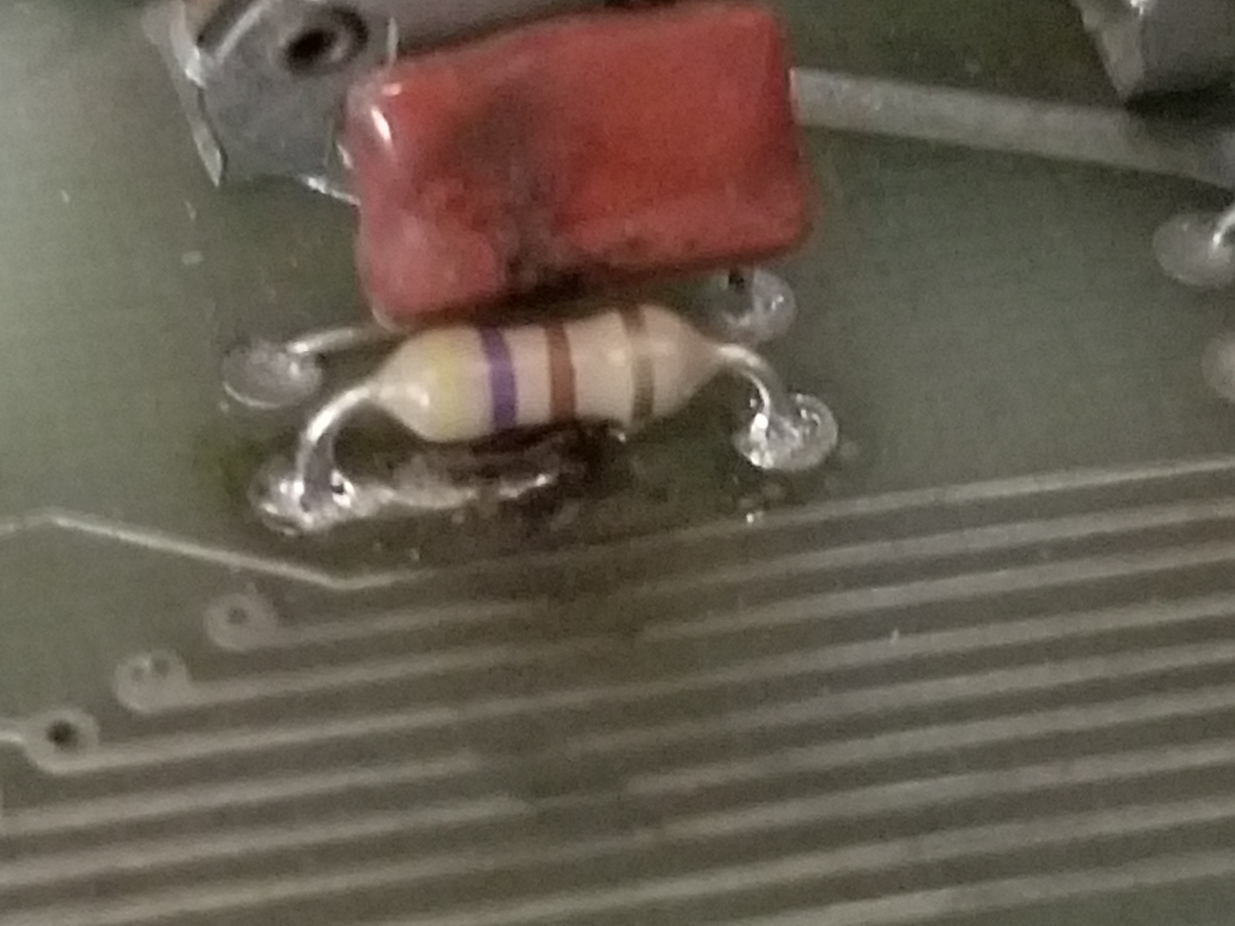
Replace the 330K resistor here: (I already did)
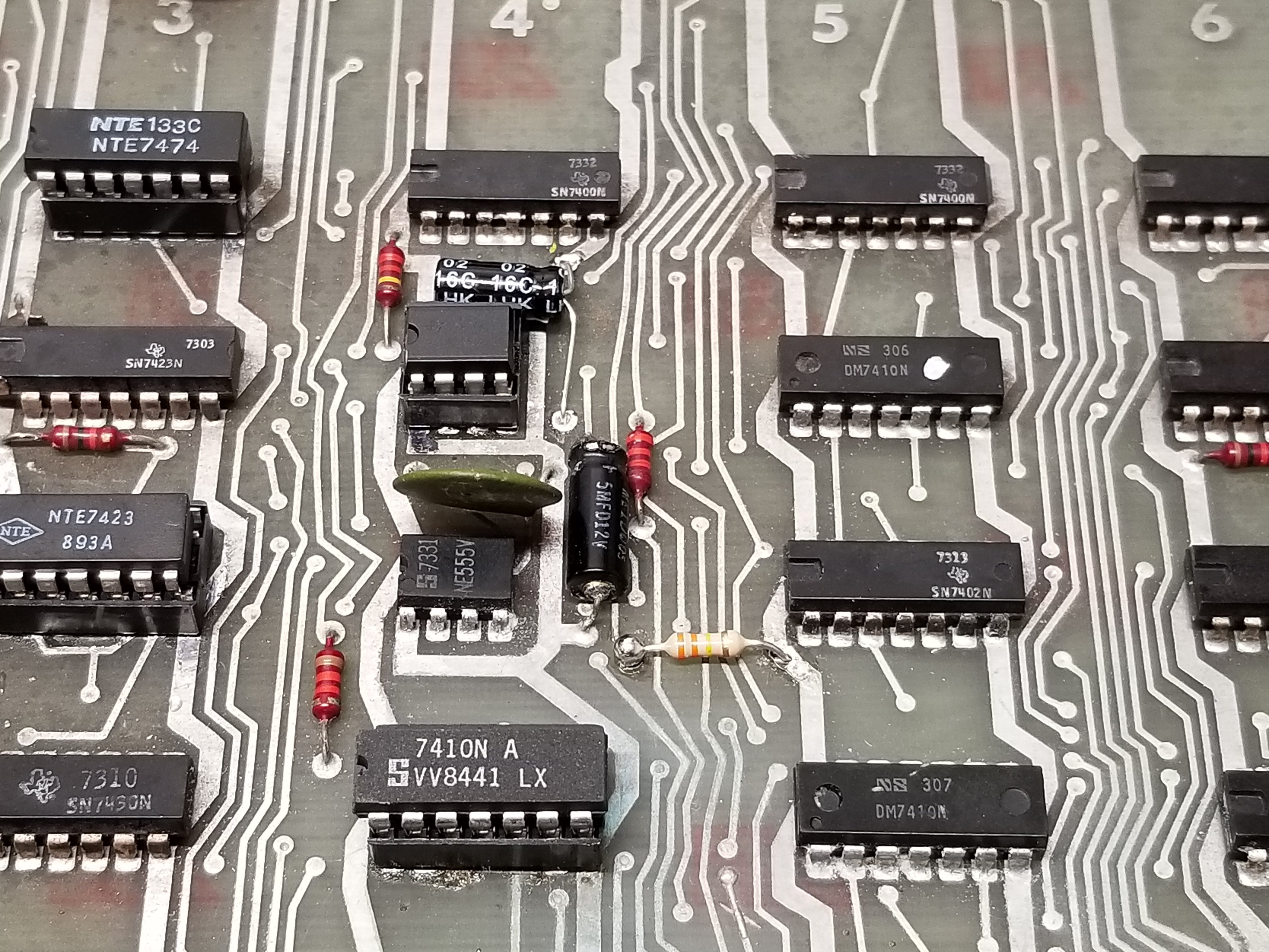
I also replaced the 220K resistor later on. I think that I actually should've replaced the 5mfd capacitor. 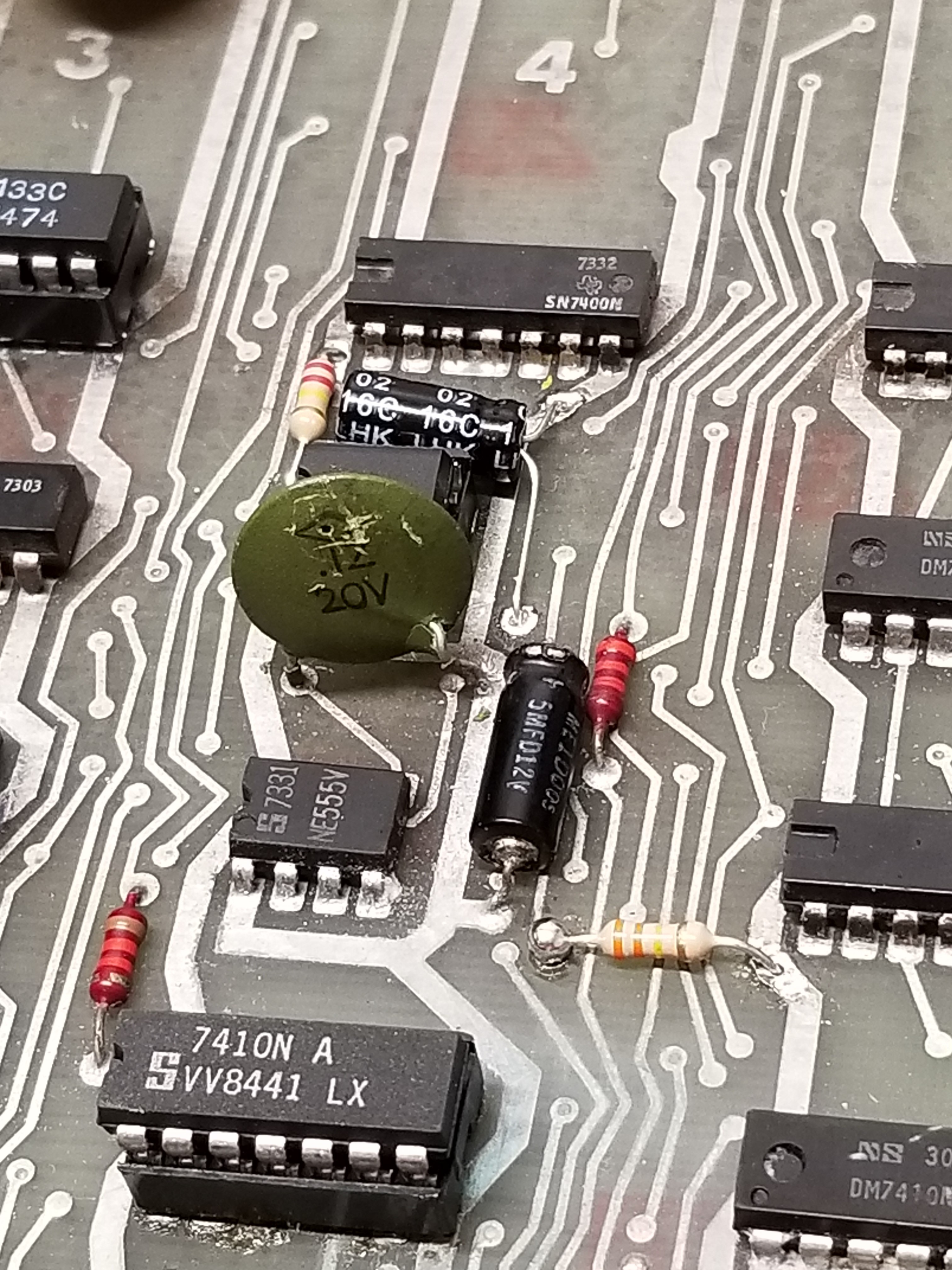
|
I looked at the Pong Doubles schematic, found the serve circuit, and tested parts. The resistor was reading 1 meg.
I pulled it out, it measured ~330K. It still fixed it. Maybe it was on its last legs?
Also: When I say I looked at the Pong Doubles schematic: It is not a good representation of the game, because it is not a "clone". The layout for the board and components are different. Simple circuits sometimes use the same components, and even though the parts aren't at the same grid location, they still sometimes are in the circuit. I just got lucky that they were for the Score and Serve timers. |
Found and repaired 6/25/18.
I stupidly put in a 330 ohm resistor by accident. The ball served at lightspeed each time it went off the side. 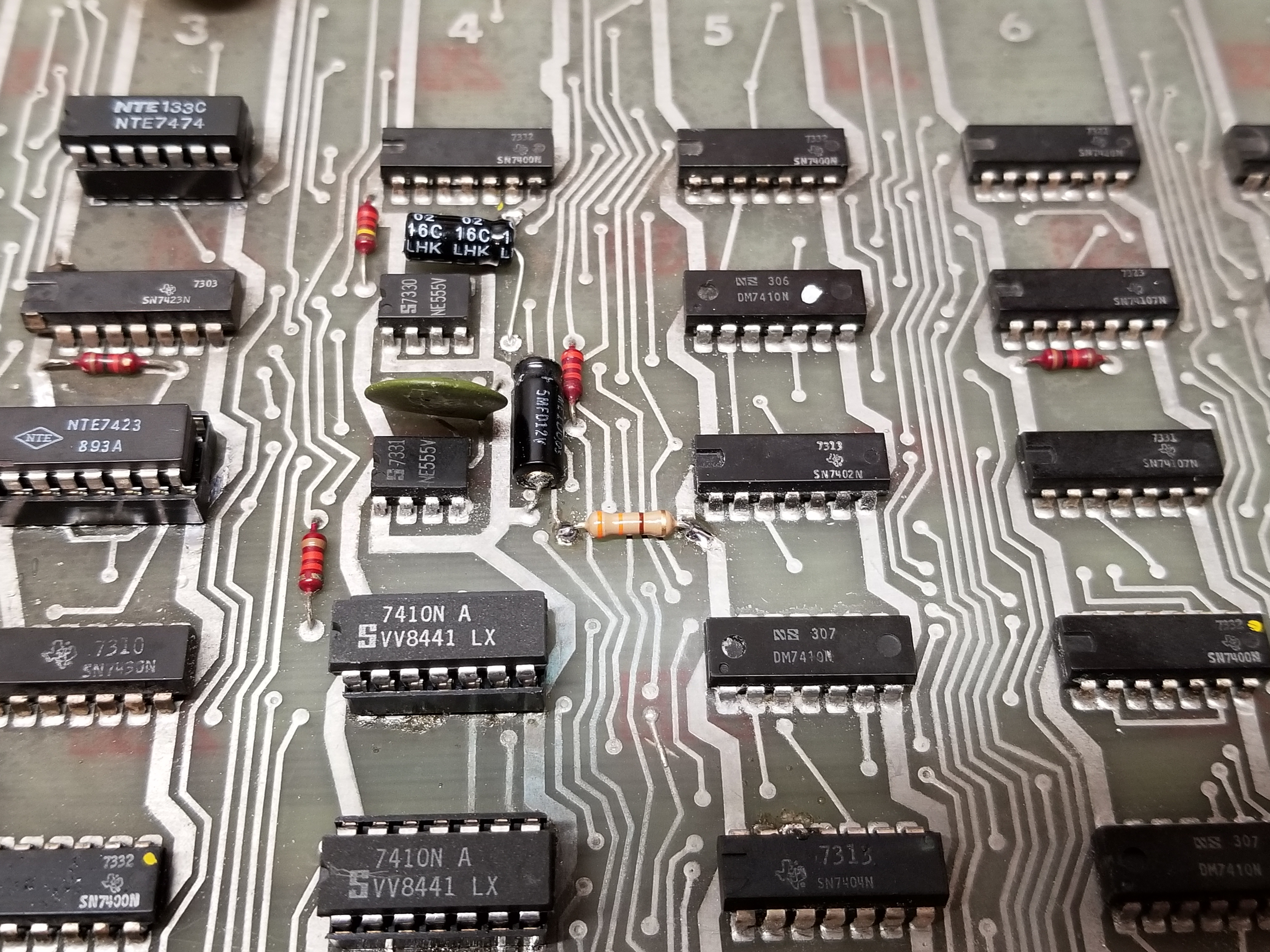
|
| Game emits buzzing sound annoyingly long. More than 10 seconds, to be exact. | I shot a video of the bad sound:
I shot a video of the "fixed" sound: Edit: Here it is after actually being fixed: |
Bad 555 timer at G4. (Actually, it was working. Replacing it somehow fixed it anyway...)
|
I looked at the Pong Doubles schematic, I checked all the other parts, they were either good or already replaced.
(I recapped the board at one point, except for 2 I didn't have...)
|
Found and repaired 6/25/18. |
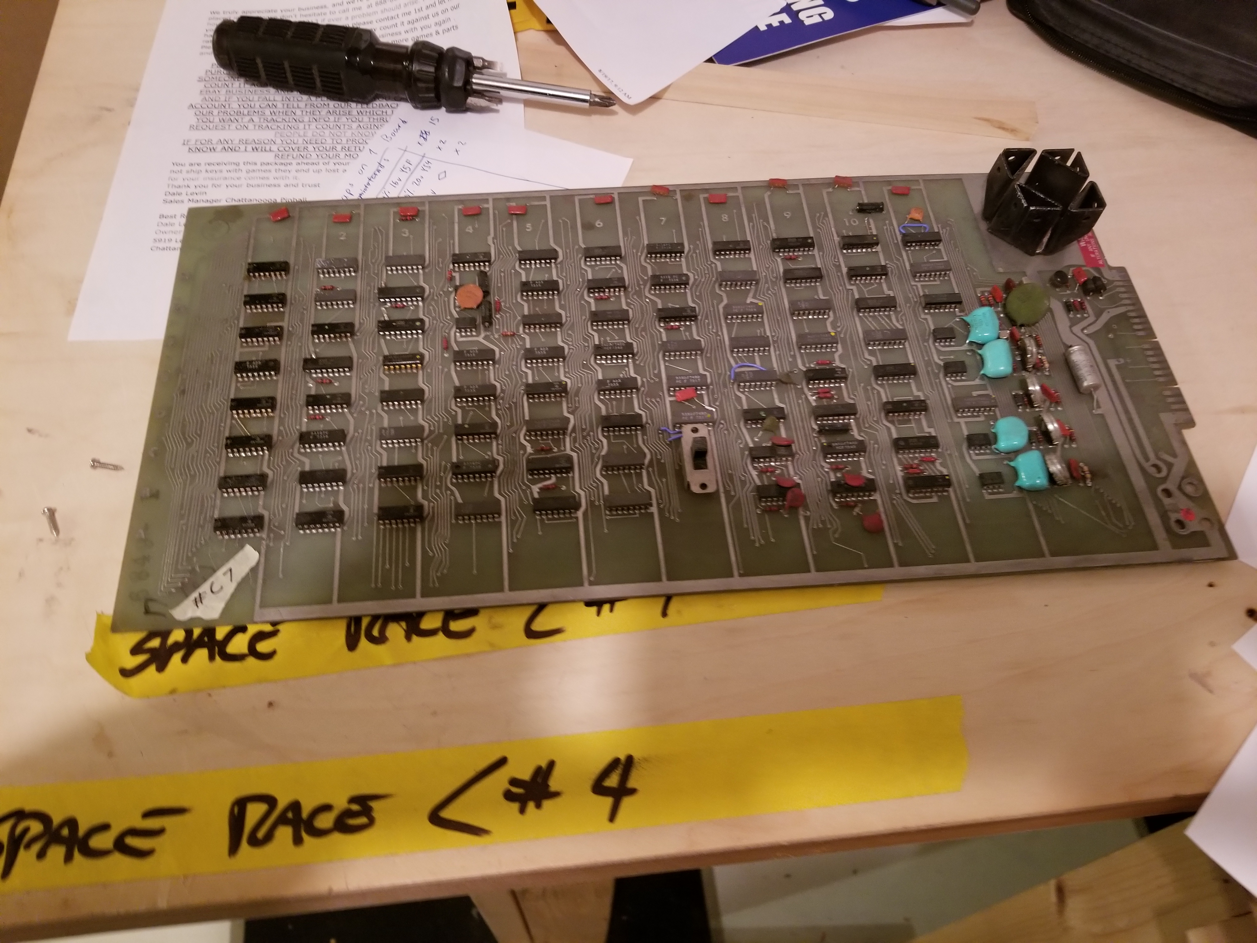
Repairs for the board marked "C-7"
| The Problem: | Game Screen: | Solution: | How I found it: | Misc. |
| Some resistors apparently caught on fire... | PCB images:
That trace is not broken, that is the smoked guts of a 40 year old resistor on a PCB. 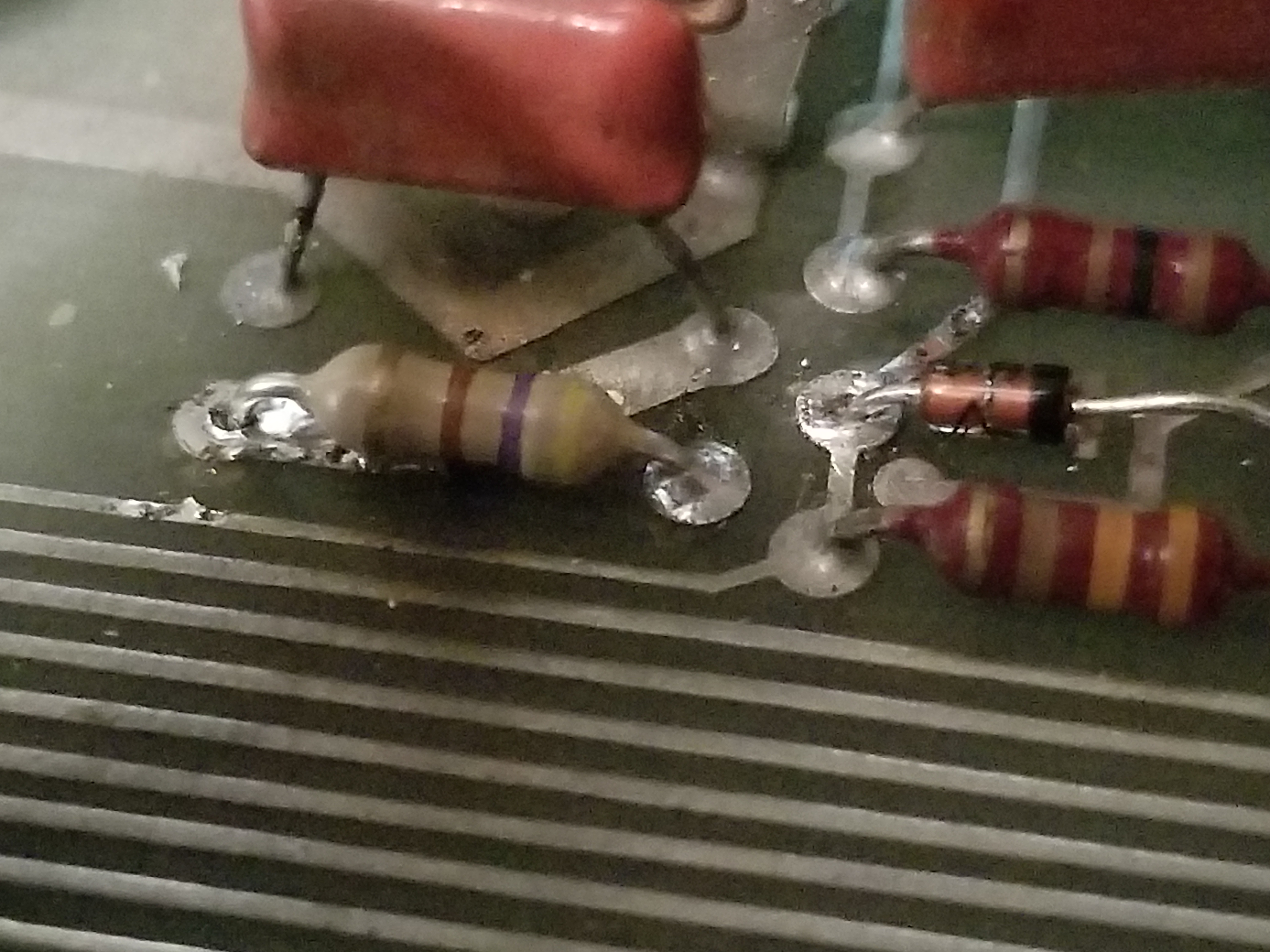
|
The resistors caught on fire, so replace them. It's not that hard. | I looked at the board, two resistors had smoked up the board, and were falling apart. | I did this repair without taking "before" pictures. The resistors used to be red, but they were scorched, black and grey in the center. They were flaking onto the PCB.
I did this repair before the card edge connectors arrived for me to "properly" test it. |
| The board does nothing. | It's dead. What's the point? | How I found it: | There is about 0 ohms of resistance between the power and ground traces, but the game still does stuff... weird. |
Chip Locations on Olympic Tennis
Update 8/30/2020
There is no manual for this game on the internet. It is just another one of those unloved pong clones. However, the people who cloned Tennis Tourney made enough changes to the board layout that people without a manual will have a hard time fixing their clones. To make matters worse, some chips' part numbers and other markings have completely faded off, making repair impossible. Since I'm probably the only person in the world with two of these things, I thought it would be good to compile and make this information availible:
The edge connector is on the right.
| ROW: | |||||||||||
| H | 7400 | 74107 | 7474 | 7400 | 7400 | 7420 | 74161 | 7400 | 7425* | 7425* | 74121 |
| G | 7402 | 7474 | 7425* | 555 | 7410 | 74107 | 74161 | 74107 | 7420 | 7400 | 7493 |
| F | 7493 | 7400 | 7425* | 555 | 7402 | 74107 | 7430 | 7493 | 7493 | 7420 | 7404 |
| E | 7410 | 7425* | 7430 | 7410 | 7410 | 7400 | 7474 | 7493 | 7493 | 7493 | 555 |
| D | 7404 | 7402 | 7400 | 7410 | 7404 | 7410 | 7490 | 7474 | 7474 | 7404 | 555 |
| C | 7400 | 74161 | 7474 | 7450 | 7448 | 74107 | 7490 | 7400 | 7425* | 7400 | 7493 |
| B | 7450 | 74107 | 7400 | 74161 | 7483 | 74153 | SWITCH | 7402 | 7410 | 7420 | 555 |
| A | 7400 | 74107 | 7450 | 7474 | 7486 | 74153 | 7404 | 7400 | 7493 | 555 | |
| 1 | 2 | 3 | 4 | 5 | 6 | 7 | 8 | 9 | 10 | 11 |
*Note: On Olympic Tennis, it appears that there was a shortage of the 7425 chip throughout the production run. Whenever the chip wasn't availible, a 7423 was shoehorned into the same spot like shown below. The 7423s and 7425s are dispersed randomly throughout the boards I have.
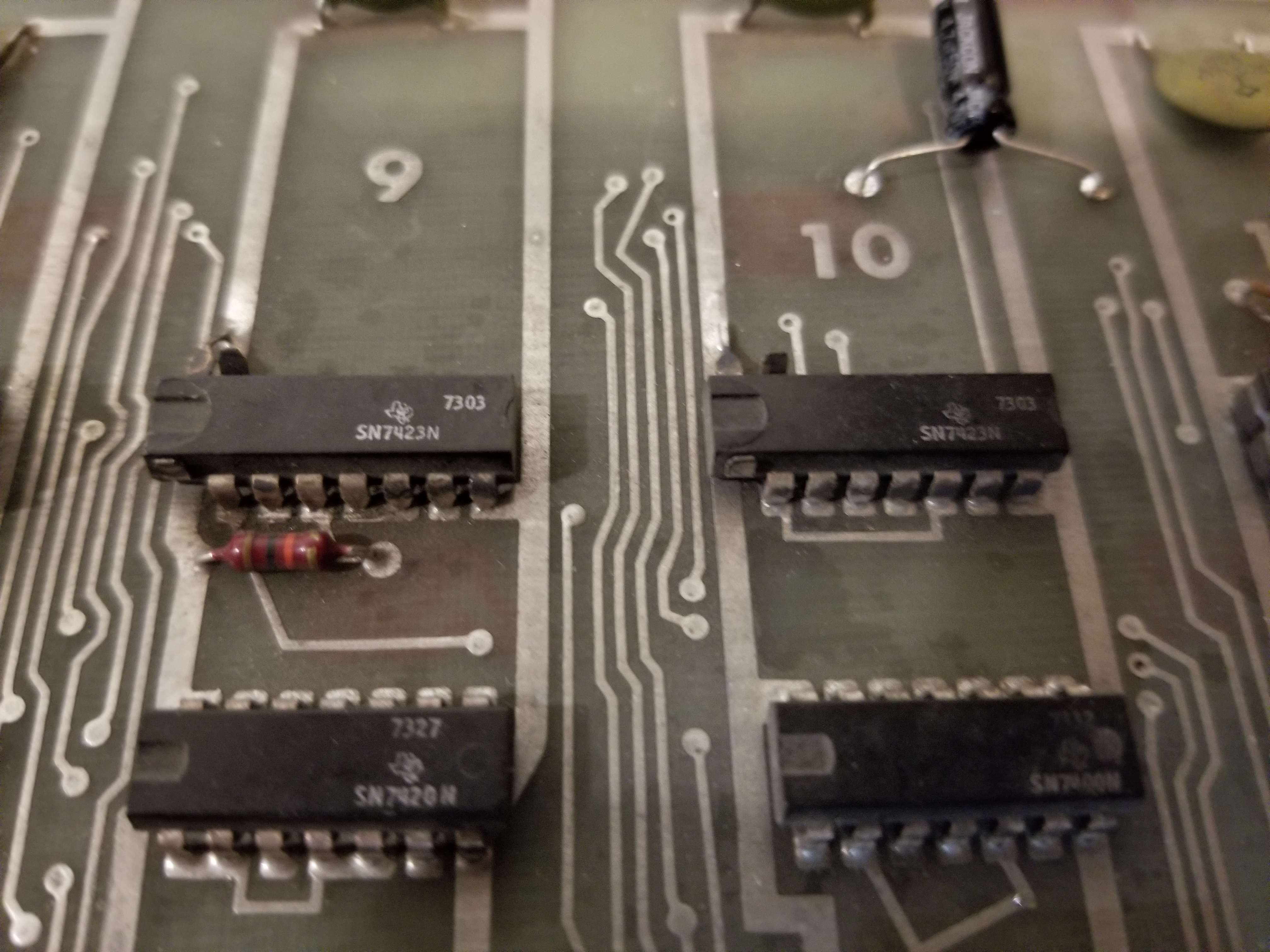
(Clip off pins 1 and 15, solder pin 16 to the power rail. It makes sense if you compare the datasheets.)
This page was last updated 1/5/2022
Spelling, grammar, and readability corrections.
This page was probably published sometime in late June of 2018.